车牌检测实验
前言
在上一章节中,我们已经学习了如何在CanMV下使用CanMV AI视觉开发框架和MicroPython编程方法实现物体分割的功能,本章将通过车牌检测实验,介绍如何使用CanMV AI视觉开发框架和MicroPython编程实现车牌区域的检测。在本实验中,我们首先采集摄像头捕获的图像,然后经过图像预处理、模型推理和输出处理结果等一系列步骤,系统将识别到图像中存在车牌的区域,并绘制绿色的矩形框将车牌区域包围,最后,将结果绘制并显示在显示器上。通过本章的学习,读者将掌握如何在CanMV下使用CanMV AI视觉开发框架和MicroPython编程方法实现车牌检测的功能。
AI开发框架介绍
为了简化AI开发流程并降低AI开发难度,CanMV官方针对K230D专门搭建了AI开发框架,有关AI开发框架的介绍,请见CanMV AI开发框架
硬件设计
例程功能
- 获取摄像头输出的图像,然后将图像输入到CanMV K230D的AI模型进行推理。本实验使用了一个车牌检测模型,该模型用于检测图像中所有的车牌,当图像中存在车牌时,系统能够识别出车牌在图像中的区域,并绘制绿色矩形框将车牌区域包围。最后,将处理后的图像显示在LCD上。
硬件资源
- 本章实验内容主要讲解K230D的神经网络加速器KPU的使用,无需关注硬件资源。
原理图
- 本章实验内容主要讲解K230D的神经网络加速器KPU的使用,无需关注原理图。
实验代码
from libs.PipeLine import PipeLine, ScopedTiming
from libs.AIBase import AIBase
from libs.AI2D import Ai2d
import os
import ujson
from media.media import *
from media.sensor import *
from time import *
import nncase_runtime as nn
import ulab.numpy as np
import time
import utime
import image
import random
import gc
import sys
import aidemo
# 自定义车牌检测类
class LicenceDetectionApp(AIBase):
# 初始化函数,设置车牌检测应用的参数
def __init__(self, kmodel_path, model_input_size, confidence_threshold=0.5, nms_threshold=0.2, rgb888p_size=[224,224], display_size=[1920,1080], debug_mode=0):
super().__init__(kmodel_path, model_input_size, rgb888p_size, debug_mode) # 调用基类的初始化函数
self.kmodel_path = kmodel_path # 模型路径
# 模型输入分辨率
self.model_input_size = model_input_size
# 分类阈值
self.confidence_threshold = confidence_threshold
self.nms_threshold = nms_threshold
# sensor给到AI的图像分辨率
self.rgb888p_size = [ALIGN_UP(rgb888p_size[0], 16), rgb888p_size[1]]
# 显示分辨率
self.display_size = [ALIGN_UP(display_size[0], 16), display_size[1]]
self.debug_mode = debug_mode
# Ai2d实例,用于实现模型预处理
self.ai2d = Ai2d(debug_mode)
# 设置Ai2d的输入输出格式和类型
self.ai2d.set_ai2d_dtype(nn.ai2d_format.NCHW_FMT, nn.ai2d_format.NCHW_FMT, np.uint8, np.uint8)
# 配置预处理操作,这里使用了pad和resize,Ai2d支持crop/shift/pad/resize/affine
def config_preprocess(self, input_image_size=None):
with ScopedTiming("set preprocess config", self.debug_mode > 0):
# 初始化ai2d预处理配置,默认为sensor给到AI的尺寸,可以通过设置input_image_size自行修改输入尺寸
ai2d_input_size = input_image_size if input_image_size else self.rgb888p_size
self.ai2d.resize(nn.interp_method.tf_bilinear, nn.interp_mode.half_pixel)
self.ai2d.build([1,3,ai2d_input_size[1],ai2d_input_size[0]],[1,3,self.model_input_size[1],self.model_input_size[0]])
# 自定义当前任务的后处理
def postprocess(self, results):
with ScopedTiming("postprocess", self.debug_mode > 0):
# 对检测结果进行后处理
det_res = aidemo.licence_det_postprocess(results, [self.rgb888p_size[1], self.rgb888p_size[0]], self.model_input_size, self.confidence_threshold, self.nms_threshold)
return det_res
# 绘制检测结果到屏幕上
def draw_result(self, pl, dets):
with ScopedTiming("display_draw", self.debug_mode > 0):
if dets:
pl.osd_img.clear() # 清除屏幕
point_8 = np.zeros((8), dtype=np.int16)
for det in dets:
# 将检测框坐标从sensor图像分辨率转换为显示分辨率
for i in range(4):
x = det[i * 2 + 0] / self.rgb888p_size[0] * self.display_size[0]
y = det[i * 2 + 1] / self.rgb888p_size[1] * self.display_size[1]
point_8[i * 2 + 0] = int(x)
point_8[i * 2 + 1] = int(y)
# 在屏幕上绘制检测框
for i in range(4):
pl.osd_img.draw_line(point_8[i * 2 + 0], point_8[i * 2 + 1], point_8[(i + 1) % 4 * 2 + 0], point_8[(i + 1) % 4 * 2 + 1], color=(255, 0, 255, 0), thickness=4)
else:
pl.osd_img.clear() # 如果没有检测结果,则清空屏幕
if __name__=="__main__":
# 显示模�式,默认"lcd"
display_mode="lcd"
display_size=[640,480]
# 模型路径
kmodel_path="/sdcard/examples/kmodel/LPD_640.kmodel"
# 其它参数设置
confidence_threshold = 0.2
nms_threshold = 0.2
rgb888p_size=[640,360]
# 初始化PipeLine
sensor = Sensor(width=1280, height=960) # 构建摄像头对象
pl = PipeLine(rgb888p_size=rgb888p_size, display_size=display_size, display_mode=display_mode)
pl.create(sensor=sensor) # 创建PipeLine实例
# 初始化自定义车牌检测实例
licence_det=LicenceDetectionApp(kmodel_path,model_input_size=[640,640],confidence_threshold=confidence_threshold,nms_threshold=nms_threshold,rgb888p_size=rgb888p_size,display_size=display_size,debug_mode=0)
licence_det.config_preprocess()
try:
while True:
os.exitpoint()
with ScopedTiming("total",1):
# 获取当前帧数据
img=pl.get_frame()
# 推理当前帧
res=licence_det.run(img)
# 打印结果
# print(res)
# 绘制结果到PipeLine的osd图像
licence_det.draw_result(pl,res)
# 显示当前的绘制结果
pl.show_image()
gc.collect()
except Exception as e:
sys.print_exception(e)
finally:
licence_det.deinit()
pl.destroy()
可以看到一开始是先定义显示模式、图像大小、模型相关的一些变量。
接着是通过初始化PipeLine,这里主要初始化sensor和display模块,配置摄像头输出两路不同的格式和大小的图像,以及设置显示模式,完成创建PipeLine实例。
然后调用自定义LicenceDetectionApp类构建车牌检测类,LicenceDetectionApp类会对AIBase接口的初始化以及使用Ai2D接口的方法定义物体分割模型输入图像的预处理方法。
最后,在一个循环中不断获取摄像头输出的RGB888格式图像帧,然后将图像输入到车牌检测模型进行推理。推理结果通过print打印出来,系统会根据检测的结果绘制绿色矩形框将车牌区域包围,并在LCD上显示处理后的图像。
运行验证
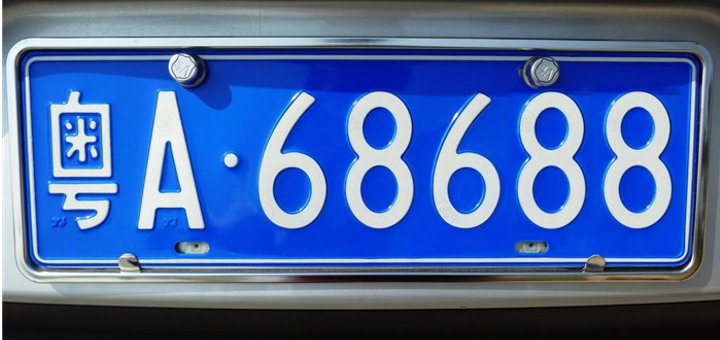
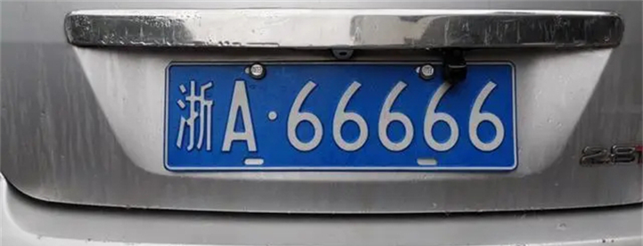
实验原图如下所示:
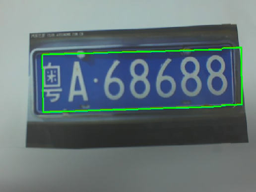
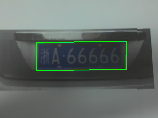
将K230D BOX开发板连接CanMV IDE,点击CanMV IDE上的“开始(运行脚本)”按钮后,将摄像头对准含有车牌的区域,让其采集到需识别的车牌,随后便能在LCD上看到摄像头输出的图像,可以看到,图像中的车牌区域会被绿色的矩形框框出,如下图所示:
点击左下角“串行终端”,可以看到“串行终端”窗口中输出了一系列信息,如下图所示:
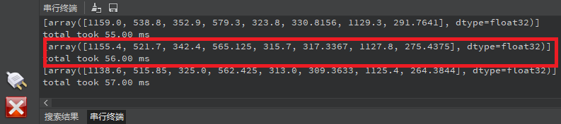
可以看到,系统每次打印输出一组数据,表示图像中存在一张车牌,这组数据一共有8个数据,表示[x1,y1,x2,y2,x3,y3,x4,y4],每两个数据表示车牌区域的4个顶点的坐标,这样就能准确定位到图像中车牌的区域。为了准确地显示在屏幕上,我们需要将这些坐标和尺寸乘以一个缩放值(即LCD显示的分辨率与RGBP888图像尺寸的比值),从而获得在LCD显示器中车牌的区域。根据获得的值绘制矩形框,即可将车牌标注出来。