人体检测实验
前言
在上一章节中,我们已经学习了如何在CanMV下使用CanMV AI视觉开发框架和MicroPython编程方法实现人脸识别的功能,本章将通过人体检测实验,介绍如何使用CanMV AI视觉开发框架和MicroPython编程实现人体检测并将检测的可信度绘制出来。在本实验中,我们首先采集摄像头捕获的图像,然后经过图像预处理、模型推理和输出处理结果等一系列步骤,系统输出图像中的所有的人体信息,完成人体检测的功能。最后,将检测结果绘制并显示在显示器上。通过本章的学习,读者将掌握如何在CanMV下使用CanMV AI视觉开发框架和MicroPython编程方法实现人体检测功能。
AI开发框架介绍
为了简化AI开发流程并降低AI开发难度,CanMV官方针对K230D专门搭建了AI开发框架,有关AI开发框架的介绍,请见CanMV AI开发框架
硬件设计
例程功能
- 获取摄像头输出的图像,然后将图像输入到CanMV K230D的AI模型进行推理。本实验使用了一个基于YOLOv5的人体检测模型,该模型用于检测图像中的人体位置并输出其可信度。通过AI推理出图像中人体的坐标,我们在图像中绘制矩形框进行标注,并在矩形框的上方显示人体检测的可信度。最后,将处理后的图像显示在LCD上。
硬件资源
- 本章实验内容主要讲解K230D的神经网络加速器KPU的使用,无需关注硬件资源。
原理图
- 本章实验内容主要讲解K230D的神经网络加速器KPU的使用,无需关注原理图。
实验代码
from libs.PipeLine import PipeLine, ScopedTiming
from libs.AIBase import AIBase
from libs.AI2D import Ai2d
import os
import ujson
from media.media import *
from media.sensor import *
from time import *
import nncase_runtime as nn
import ulab.numpy as np
import time
import utime
import image
import random
import gc
import sys
import aicube
# 自定义人体检测类
class PersonDetectionApp(AIBase):
def __init__(self,kmodel_path,model_input_size,labels,anchors,confidence_threshold=0.2,nms_threshold=0.5,nms_option=False,strides=[8,16,32],rgb888p_size=[224,224],display_size=[1920,1080],debug_mode=0):
super().__init__(kmodel_path,model_input_size,rgb888p_size,debug_mode)
self.kmodel_path=kmodel_path
# 模型输入分辨率
self.model_input_size=model_input_size
# 标签
self.labels=labels
# 检测anchors设置
self.anchors=anchors
# 特征图降采样倍数
self.strides=strides
# 置信度阈值设置
self.confidence_threshold=confidence_threshold
# nms阈值设置
self.nms_threshold=nms_threshold
self.nms_option=nms_option
# sensor给到AI的图像分辨率
self.rgb888p_size=[ALIGN_UP(rgb888p_size[0],16),rgb888p_size[1]]
# 显示分辨率
self.display_size=[ALIGN_UP(display_size[0],16),display_size[1]]
self.debug_mode=debug_mode
# Ai2d实例,用于实现模型预处理
self.ai2d=Ai2d(debug_mode)
# 设置Ai2d的输入输出格式和类型
self.ai2d.set_ai2d_dtype(nn.ai2d_format.NCHW_FMT,nn.ai2d_format.NCHW_FMT,np.uint8, np.uint8)
# 配置预处理操作,这里使用了pad和resize,Ai2d支持crop/shift/pad/resize/affine,具体代码请打开/sdcard/app/libs/AI2D.py查看
def config_preprocess(self,input_image_size=None):
with ScopedTiming("set preprocess config",self.debug_mode > 0):
# 初始化ai2d预处理配置,默认为sensor给到AI的尺寸,您可以通过设置input_image_size自行修改输入尺寸
ai2d_input_size=input_image_size if input_image_size else self.rgb888p_size
top,bottom,left,right=self.get_padding_param()
self.ai2d.pad([0,0,0,0,top,bottom,left,right], 0, [0,0,0])
self.ai2d.resize(nn.interp_method.tf_bilinear, nn.interp_mode.half_pixel)
self.ai2d.build([1,3,ai2d_input_size[1],ai2d_input_size[0]],[1,3,self.model_input_size[1],self.model_input_size[0]])
# 自定义当前任务的后处理
def postprocess(self,results):
with ScopedTiming("postprocess",self.debug_mode > 0):
# 这里使用了aicube模型的后处理接口anchorbasedet_post_preocess
dets = aicube.anchorbasedet_post_process(results[0], results[1], results[2], self.model_input_size, self.rgb888p_size, self.strides, len(self.labels), self.confidence_threshold, self.nms_threshold, self.anchors, self.nms_option)
return dets
# 绘制结果
def draw_result(self,pl,dets):
with ScopedTiming("display_draw",self.debug_mode >0):
if dets:
pl.osd_img.clear()
for det_box in dets:
x1, y1, x2, y2 = det_box[2],det_box[3],det_box[4],det_box[5]
w = float(x2 - x1) * self.display_size[0] // self.rgb888p_size[0]
h = float(y2 - y1) * self.display_size[1] // self.rgb888p_size[1]
x1 = int(x1 * self.display_size[0] // self.rgb888p_size[0])
y1 = int(y1 * self.display_size[1] // self.rgb888p_size[1])
x2 = int(x2 * self.display_size[0] // self.rgb888p_size[0])
y2 = int(y2 * self.display_size[1] // self.rgb888p_size[1])
if (h<(0.1*self.display_size[0])):
continue
if (w<(0.25*self.display_size[0]) and ((x1<(0.03*self.display_size[0])) or (x2>(0.97*self.display_size[0])))):
continue
if (w<(0.15*self.display_size[0]) and ((x1<(0.01*self.display_size[0])) or (x2>(0.99*self.display_size[0])))):
continue
pl.osd_img.draw_rectangle(x1 , y1 , int(w) , int(h), color=(255, 0, 255, 0), thickness = 2)
pl.osd_img.draw_string_advanced( x1 , y1-50,32, " " + self.labels[det_box[0]] + " " + str(round(det_box[1],2)), color=(255,0, 255, 0))
else:
pl.osd_img.clear()
# 计算padding参数
def get_padding_param(self):
dst_w = self.model_input_size[0]
dst_h = self.model_input_size[1]
input_width = self.rgb888p_size[0]
input_high = self.rgb888p_size[1]
ratio_w = dst_w / input_width
ratio_h = dst_h / input_high
if ratio_w < ratio_h:
ratio = ratio_w
else:
ratio = ratio_h
new_w = (int)(ratio * input_width)
new_h = (int)(ratio * input_high)
dw = (dst_w - new_w) / 2
dh = (dst_h - new_h) / 2
top = int(round(dh - 0.1))
bottom = int(round(dh + 0.1))
left = int(round(dw - 0.1))
right = int(round(dw - 0.1))
return top, bottom, left, right
if __name__=="__main__":
# 显示模式,默认"lcd"
display_mode="lcd"
display_size=[640,480]
# 模型路径
kmodel_path="/sdcard/examples/kmodel/person_detect_yolov5n.kmodel"
# �其它参数设置
confidence_threshold = 0.2
nms_threshold = 0.6
rgb888p_size=[640,360]
labels = ["person"]
anchors = [10, 13, 16, 30, 33, 23, 30, 61, 62, 45, 59, 119, 116, 90, 156, 198, 373, 326]
# 初始化PipeLine
sensor = Sensor(width=1280, height=960) # 构建摄像头对象
pl = PipeLine(rgb888p_size=rgb888p_size, display_size=display_size, display_mode=display_mode)
pl.create(sensor=sensor) # 创建PipeLine实例
# 初始化自定义人体检测实例
person_det=PersonDetectionApp(kmodel_path,model_input_size=[640,640],labels=labels,anchors=anchors,confidence_threshold=confidence_threshold,nms_threshold=nms_threshold,nms_option=False,strides=[8,16,32],rgb888p_size=rgb888p_size,display_size=display_size,debug_mode=0)
person_det.config_preprocess()
try:
while True:
os.exitpoint()
with ScopedTiming("total",1):
# 获取当前帧数据
img=pl.get_frame()
# 推理当前帧
res=person_det.run(img)
# 打印结果
# print(res)
# 绘制结果到PipeLine的osd图像
person_det.draw_result(pl,res)
# 显示当前的绘制结果
pl.show_image()
gc.collect()
except Exception as e:
sys.print_exception(e)
finally:
person_det.deinit()
pl.destroy()
可以看到一开始是先定义显示模式、图像大小、模型相关的一些变量。
接着是通过初始化PipeLine,这里主要初始化sensor和display模块,配置摄像头输出两路不同的格式和大小的图像,以及设置显示模式,完成创建PipeLine实例。
然后调用自定义PersonDetectionApp类构建人体检测任务类,PersonDetectionApp类会对AIBase接口的初始化以及使用Ai2D接口的方法定义人体检测模型输入图像的预处理方法。
最后在一个循环中不断地获取摄像头输出的RGBP888格式的图像帧,然后将图像输入到人体检测模型进行推理,然后将推理结果通过print打印,同时通过结果信息将人体信息通过矩形框绘制到图像上,并在LCD上显示图像。
运行验证
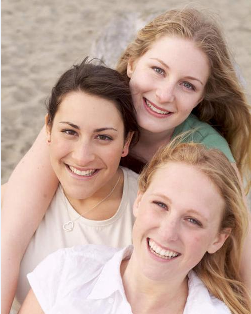
实验原图如下所示:
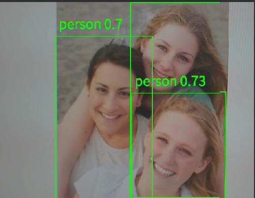
将K230D BOX开发板连接CanMV IDE,点击CanMV IDE上的“开始(运行脚本)”按钮后,将摄像头对准人体图,让其采集到人体图像,随后便能在LCD上看到摄像头输出的图像,同时图像中的人体用矩形框标注并在矩形框上方显示人体的可信度,如下图所示:
点击左下角“串行终端”,可以看到“串行终端”窗口中输出了一系列信息,如下图所示:
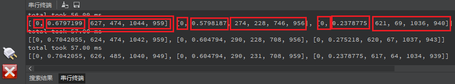
可以看到,二维数组中存在三个元素,每个元素表示检测到图像中存在一个人体。每个元素包含6个数据,可以表示为 [label,prob,x1, y1, x2, y2] ,第一个label是标签,与输入模型的标签顺序有关,prob表示目标人体的可信度,人体检测模型只有person一个标签,序号为0,x1、y1、x2、y2表示人体在输入的RGBP888图像中的起点坐标和终点坐标。这样,我们就可以确定这个人体在RGBP888图像中的位置和可信度。为了准确地显示在屏幕上,我们需要将这些坐标和尺寸乘以一个缩放值(即LCD显示的分辨率与RGBP888图像尺寸的比值),从而获得在LCD显示器中人体的区域。根据获得的值绘制矩形框,即可将人体标注出来。